
Oxygen Sensor Theory

Click images for larger
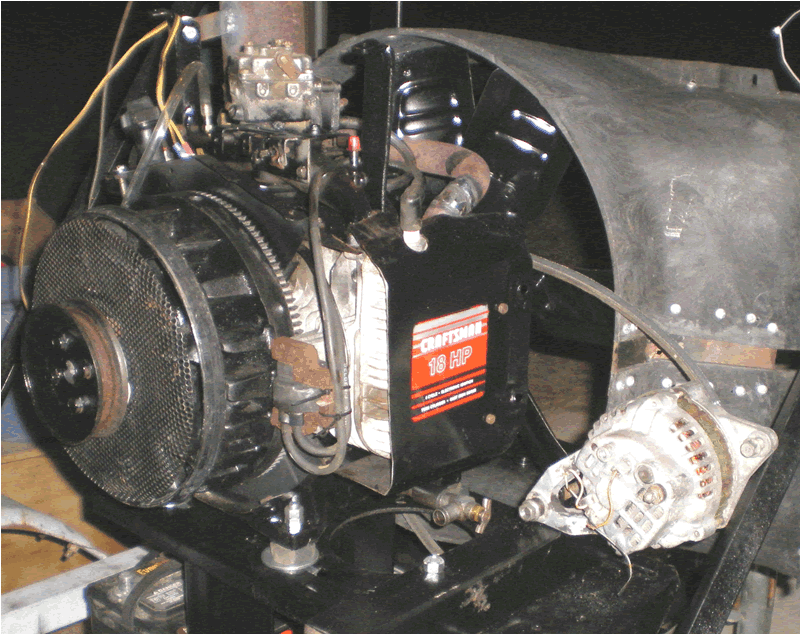
Fan Shroud
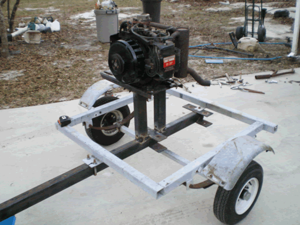
Beginning of engine stand
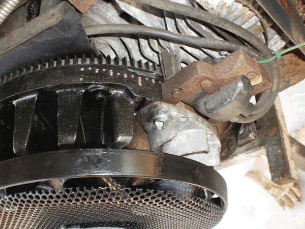
Stock ignition w/marks
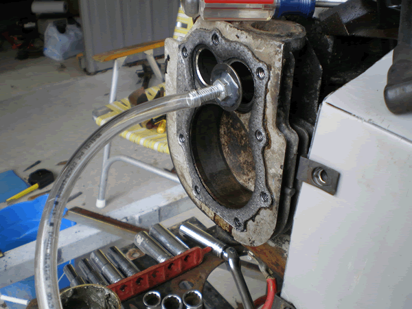
Valve lapping with hot glue
preheat bolt and valve with
propane torch, use tubing
and drill after cooled.
Narrow and Wide Band Linear Oxygen Sensor Theory
If you find any errors, or have differing opinions on this content, lets discuss it. I want this information to be as accurate as possible; otherwise it will not serve us well.
Types of Exhaust Gas Oxygen Sensors
The exhaust gas oxygen sensor is typically used in electronic fuel injection systems where the oxygen content of the exhaust gas is measured and used to automatically adjust the fuel injectors to achieve a specific air to fuel ratio (a/f/r). This is referred to as closed-loop operation. Another popular use of the oxygen sensor is to measure a/f/r while performing engine tuning for power. In this way, a speed-density fuel injection system or carbrureted engine can be corrected for varying performance conditions. The tuner can use the measured results to recalibrate the a/f/r to an acceptable ratio.
There are two basic types of OSs. Narrow band (four wires or less) and wide band (five wires or more). The narrow band sensors are designed to operate around an a/f/r of 14.7:1, and are of no use for power mixtures of a/f/r = 12.6:1. The wide band O2 sensor is designed to provide accurate indications from 10:1 through 20:1 a/f/r, which includes the power a/f/r of 12.6:1. I will now explain the operation of the narrow band sensor because it is a component part of the wide band sensor.
Narrow Band Exhaust Gas Oxygen Sensor
The narrow band sensor is depicted below. This sensor consists of a porous zirconium material with two metalic leads that are not shown in the drawing. One lead is attached to engine ground, and the other lead connects the OS output voltage back to the engine control computer. The zirconium, when exposed to outside air on one side and exhaust gas on the other side, becomes a electromotive force (voltage) generator. This form of a chemical generator uses oxygen ions to develop its output voltage potential difference between the two metalic leads. The voltage generated depends upon the oxygen difference on the two sides of the zirconium electrode, and also requires that the zirconium element be sustained at a temperature of at least 600F degrees.
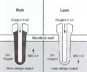
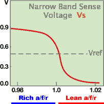
Above 600F degrees, the narrow band oxygen sensor generates an output voltage proportional to the oxygen content of the exhaust gas. This oxygen sensor compares the oxygen present in the exhaust gas to the outside atmosphere oxygen content. When the exhaust gas mixture becomes rich, there is less oxygen left because the fuel burn used up most of the oxygen. When the mixture is lean, then there is not enough fuel to use up all the oxygen, which results in unburned surplus oxygen. These rich and lean conditions cause the narrow band OS to sharply switch between 0.6VDC (600mv when rich) and 0.3VDC (300mv when lean). The reference point for this switching action is referred to as the stoichiometric point (a/f/r = 14.7:1). Refer to the voltage waveform of the narrow band graph shown below.
The stoichiometric condition of 14.7:1 a/f/r is important to automotive design because this a/f/r allows the catalytic converter to maximize its effect of reducing harmful exhaust gas emissions during the catalytic converter process. The stoich condition of engine mixture control coupled with catalytic converters is critical in reducing harmful automobile emissions. Therefore, this stoich a/f/r was the chosen reference for narrow band oxygen sensor development back in the 1980's. Stoich a/f/r is maintainable when an engine is operated at 15% or less of maximum engine power. 15% is the approximate cruise power requirement for most automobiles, and cruise is where the automobile engine operates during the majority of its use. When you push the pedal to the metal, then the engine management drops closed loop stoich measurement operation, and switches to an open loop richer a/f/r to protect the engine from detonation at high power levels.
The below graph describes the lambda value and associated voltage output from the narrow band oxygen sensor unit. Lambda is a ratio of ratios. Some engine control designs use lambda as the unit of measure for the a/f/r whereas other engine control systems use the actual a/f/r value. When the a/f/r equals 14.7 parts air to 1 part fuel, the condition of stoichiometric is achieved and lambda is equal to one. When lambda equals 0.98, then the a/f/r is 15:1. This means that the 14.7:1 divided by 15:1 has a ratio of 0.98. Likewise, an a/f/r of 14.4:1 would result in a lambda of 1.02 ( 14.7:1 divided by 14.4:1).
The narrow band sensor does not begin to generate it's full output voltage until it reaches about 600F degrees. Prior to this time the sensor is not conductive, and it is as if the circuit of the sensor is open.
Although this narrow band OS sensor is fairly cheap ($25.00), it will not serve the needs of aircraft or boat engine tuners who want sustained power levels greater than 15%. It also does not serve the needs of auto tuners who are trying to prevent engine meltdown during bursts of high performance power.
Wide Band Exhaust Gas Oxygen Sensor
The wide band sensor on the other hand does meet the high power lambda sensing requirements due to its linear nature. The wide band sensor is basically composed of two narrow band sensors within the same enclosure. The principle of operation of each sensor is the same as the narrow band sensor. What is different, is that one of the sensors is an oxygen pumping unit.
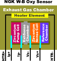
The above diagram represents a typical wide band oxygen sensor. Notice the zirconium pumping cell and the zirconium sensing cell. The zirconium cells consist of a porous substrate with a conductive lead attached to each side of the substrate. These two cells are both made from the same materials as the narrow band oxygen sensor. The difference is that the pumping cell will move oxygen through the porous substrate from left to right or from right to left based upon the direction of the pumping cell current applied to the Ip+ and Ip- leads. When current is applied to the pumping cell, it passes oxygen ions from one side of the porous substrate to the other side.
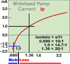
These design engineers were very crafty. They realized that if you could some how keep the sensing cell near stoichiometric condition, then the voltage generated by the sensing cell would be fairly linear. So they decided to monitor the exhaust gas in an exhaust sensing chamber (a diffusion restricted sample flow rate of the exhaust gas flow), and pump oxygen with the pumping cell into or out of the exhaust sensing chamber to reach stoichiometric condition within the exhaust sensing chamber. The oxygen ion pumping action will maintain the restricted flow exhaust sensing chamber stoich even though the exhaust gas within the exhaust gas chamber is other than stoich. Now you simply measure the pumping cell current to determine the actual wide band oxygen content of the exhaust gas chamber. Notice that the below lambda range now includes lambda's of 0.686 through 1.36 which covers an a/f/r range of 10:1 to 20:1 respectively.
The measured pumping cell current would represent the true oxygen content of the exhaust gas chamber because of the required correction taking place within the exhaust sensing chamber. As the exhaust gas slowly (restricted inlet and outlet) drifts through the exhaust sensing chamber, the pumping cell continues to add or remove oxygen to maintain stoichiometric within the exhaust sensing chamber.
For this wide band concept to work, the sensing cell must have a sealed stoichiometric reference chamber which is shown on the right side of the sensing cell in the drawing below. The sensing cell senses the oxygen content difference between the two sides of the sensing cell. Notice in the sensor diagram below, that the sensing cell has the reference cell on one side, and the exhaust sensing chamber on the other side. Therefore, the sensing cell will generate a voltage proportional to the oxygen content difference between reference chamber and the exhaust sense chamber. Those robin egg blue lines in the drawing are the electrode leads that attach to the cells and transmit electrical contact out of the oxygen sensor assembly.
The pumping cell, on the other hand, has the exhaust gas chamber on one side and the exhaust sensing chamber on the other side. The pump cell either pumps oxygen ions from the exhaust gas chamber into the exhaust sensing chamber, or it pumps oxygen ions from the exhaust sensing chamber into the exhaust gas chamber. The polarity of the pumping current determines which way the oxygen ions will transfer. In either case, the oxygen content of the exhaust sensing chamber is modified.
All we have to do now is to monitor the sense cell voltage output, and adjust the pumping current to maintain a constant sense cell output voltage which will remain within the linear range of the sense cell. What a clever design, because now the sensing cell is always operating within it's narrow band linear range of operation while the pumping cell current can indicate wide band oxygen content within the exhaust gas chamber. You may have to read this section a couple of times before it really soaks in.
Wide Band Exhaust Gas Oxygen Sensor Heater Problems
Now that we understand the basic principle of operation, lets address some physical concerns. We already acknowledged that the temperature of the sensing cell must be greater than 600F degrees before the output voltage becomes active. In the real world you want the temperature to remain between 750F degrees and 900F degrees for the most linear output voltage. To maintain these temperatures, an electric heater unit is powered to heat the sensor to the proper operating temperature range.
But there is another problem here. The exhaust gas temperature varies with engine power, and these variances affect the cell temperature regardless of the electric heater action. The exhaust gases can add to the heater power (during high engine power) and cease to add heat to the sensor during very low engine power levels. Therefore the heater circuit must be able to adjust itself for these exhaust gas flow temperature differences.
Another problem is that the sensing cell will start developing output voltage below 700F degrees while the pumping cell can't effectively move oxygen ions until it has reached 700F degrees. This means that we can not use the sense cell output voltage until the pump cell oxygen ion pumping action can control the sense cell output voltage. So we need a fast heater during engine start up, and a detection system to determine when the wide band oxygen sensor output voltage is valid.
Many WBOS controllers out there do not address the exhaust gas temperature fluctuations, and simply apply a fixed electrical power to the heater unit. They are branded as "non-scientific" models. The more accurate models must incorporate solutions to the temperature problems described above.
Another concern is the factory established calibration resistor which is intended to compensate for manufacturing differences between units. This calibration resistor value will indicate a correction factor required for the pumping cell and the sensing cell interaction during operation.
Last of all, exhaust gas back pressure can have an effect upon the sense cell output. This has to do with the porosity of the sense cell. If the cell material has pores to small, then exhaust gases will be restricted, and exhaust back pressure will vary the effectiveness of the pumping cell. If the pumping cell effectiveness changes, then the pumping cell current has a varying effect upon the sense cell. If the pumping cell has pores that are to large, then exhaust gas contaminates can get lodged into the pores and once again reduce the pumping cell effectiveness.
OS manufacturer's attempt to select the optimum pore size, which reduces the effect of exhaust gas back pressure without contaminate problems. This optimum pore size is hard to maintain during volume manufacturing. Highly accurate OS controllers may want to consider this exhaust gas back pressure in the OS measurement process, if the back pressure is significant. High performance engines usually have mild back pressure and are not affected to any significant degree by exhaust gas back pressure changes to the OS measurements.
Wide Band Exhaust Gas Oxygen Sensor Controllers
There are a couple of WBOS sensors available at a current price of about $120.00 each. In addition to being expensive, these sensors require elaborate heater and charge pump control as described above. Controllers for these wide-band OS sensors vary in price from $100.00 through $1,000.00, plus the sensor cost, depending upon the degree of accuracy required.
contact Lynn and let him know what you would like to contribute.
Return to top of page. Return to HomePage
Copyright
© 2009 by Lynn W. Graves
Reproduction or republication for commercial use
prohibited without express written permission
See website rules for further legal information
Website owned and operated by Lynn W. Graves.
Last updated (29Dec08
), lynn@whatifdyno.com