
Testing Procedures

Click images for larger
Fan Shroud
Beginning of engine stand
Stock ignition w/marks
Valve lapping with hot glue
preheat bolt and valve with
propane torch, use tubing
and drill after cooled.
Current Test Procedure Data Capture Worksheet:
This is an ongoing effort and the current worksheet can be displayed by clicking here. This worksheet is in PDF file format.
Use same fuel source for each comparison test:
The same gasoline fuel source must be used for each comparison test. Always ensure there is enough fuel in the storage container to complete all tests for that day. This will ensure the same fuel chemistry along with the same atmospheric conditions and resultant load conditions.
Baseline MBT and AFR before each type of fuel consumption test:
MBT is the maximum brake torque for this particular engine load and atmospheric conditions. With an air propeller load, the maximum propeller RPM is achieved at the MBT ignition timing point. Bring the engine up to baseline RPM. Adjust ignition timing to MBT (maximum RPM), then re-adjust RPM to baseline. Adjust the AFR (air-fuel-ratio) to baseline using the wide-band oxygen sensor. Re-adjust the RPM setting to baseline. Confirm that both AFR and MBT are both adjusted properly for the baseline RPM. Now accurate fuel consumption measurement can take place. A strobe timing light will be used to measure and record the current timing in degrees BTDC for the baseline MBT adjustment for each fuel.
Fuel Consumption Measurement:
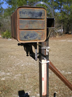 The
picture to the right shows our fuel consumption measuring technique. The
yard stick is calibrated in centimeters. We have a fuel shut-off valve
that stops fuel flow from the fuel tank. We also have a tee connection
which vents the fuel line to the top of the fuel tank. In this way, when
the fuel flow is shut-off at the fuel tank, the fuel hose can draw air
from the vent hose going to the top of the fuel tank. Now we simply measure
the fuel drop in the clear fuel line for a give time interval. This carb
has a fuel pump built into the carb which will keep the carb bowl filled.
This is a diaphram pump which works off the engine crankcase pressure.
The
picture to the right shows our fuel consumption measuring technique. The
yard stick is calibrated in centimeters. We have a fuel shut-off valve
that stops fuel flow from the fuel tank. We also have a tee connection
which vents the fuel line to the top of the fuel tank. In this way, when
the fuel flow is shut-off at the fuel tank, the fuel hose can draw air
from the vent hose going to the top of the fuel tank. Now we simply measure
the fuel drop in the clear fuel line for a give time interval. This carb
has a fuel pump built into the carb which will keep the carb bowl filled.
This is a diaphram pump which works off the engine crankcase pressure.
Fuel Chemistry impact upon engine intake manifold vacuum:
As you may know, the engine intake manifold vacuum measurement is indicative of engine load. As the engine load increases, the intake manifold vacuum decreases. After setting the test baseline as described above for gasoline, it will be interesting to find out what impact it has upon engine vacuum. When HHO is added it is expected that engine efficiency will increase, in which case engine RPM may increase while vacuum may also increase. Time will tell.
Oxygen Sensor response to fuel changes:
The wide-band oxygen sensor will be used to measure and record the air/fuel/ratio changes caused by the HHO enhancement. The narrow-band oxygen sensor will be used to measure and record the narrow-band oxygen sensor voltage offset caused by the HHO enhancement. These measurements will be taken before readjusting the baseline for the addition of HHO enhancement. Once the new baseline for HHO enhancement has been set, then these sensors will be measured and recorded again.
Exhaust Gas Temperature and Cylinder Head Temperature:
It is anticipated that the HHO enhancement will reduce exhaust gas temperature and cylinder head temperature for the same load (same RPM) as compared to non-HHO enhancement. This will be measured and recorded before and after the HHO enhancement baseline re-adjustment.
Effect of various HHO percentages of air intake volume:
We want to find out what percentage of HHO has the most effect upon engine efficiency. To determine this, we must run tests with varying percentages of HHO in the intake manifold. Accurate measurement of this ratio will be attempted by measuring the intake airflow without HHO and the air intake flow using HHO. The following formula is assumed as accurate:
Airflow (given RPM) minus Airflow (same RPM with HHO via another port) = Difference Airflow
Airflow (same RPM with HHO via another port) = Net Ariflow
Percentage of HHO = Difference Airflow divided by Net Airflow
Example:
Engine air intake plumbing pulls 10 Liter/min on gasoline at 3000 RPM
Engine air intake plumbing pulls 9.5 Liter/min with HHO at 3000 RPM (net
airflow)
HHO must be providing 0.5 Liter/min through the separate HHO intake plumbing
HHO percentage = 0.5 / 9.5 = 5.26% of the mixture being ingested by the
engine.
We can control the HHO flow using an adjustable valve on the HHO plumbing. Now we can measure the fuel consumption for the same load with varying percentages of HHO enhancement. This same valve can be used to turn off HHO enhancement. In other words, we can blip off the HHO and see what effect that short duration of HHO has upon engine dynamics as defined above.
contact Lynn and let him know what you would like to contribute.
Return to top of page. Return to HomePage
Copyright
© 2009 by Lynn W. Graves
Reproduction or republication for commercial use
prohibited without express written permission
See website rules for further legal information
Website owned and operated by Lynn W. Graves.
Last updated (25feb09}
), lynn@whatifdyno.com