
Combustion Info for Gasoline

Click images for larger
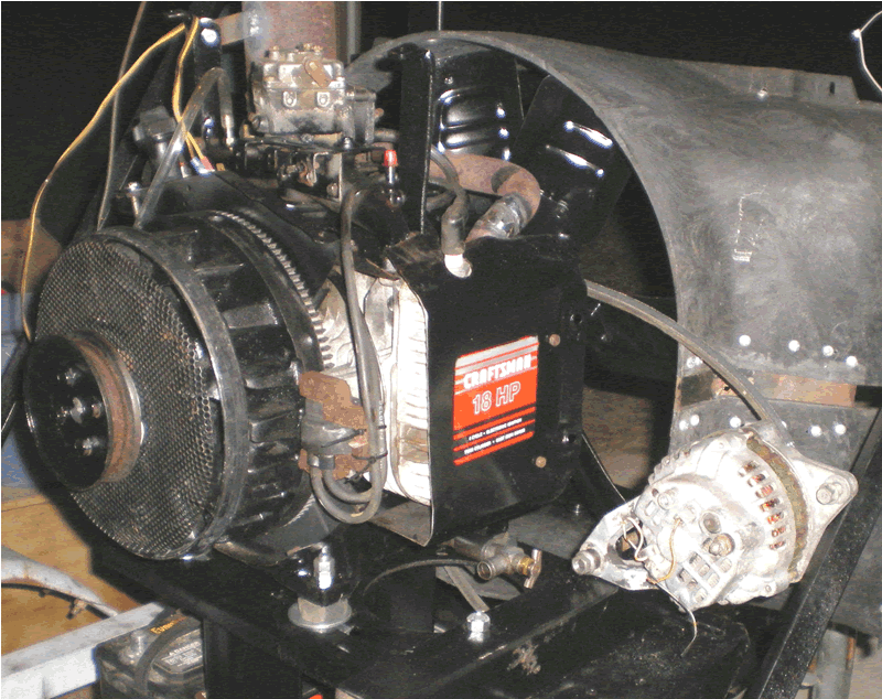
Fan Shroud
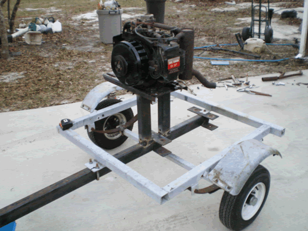
Beginning of engine stand
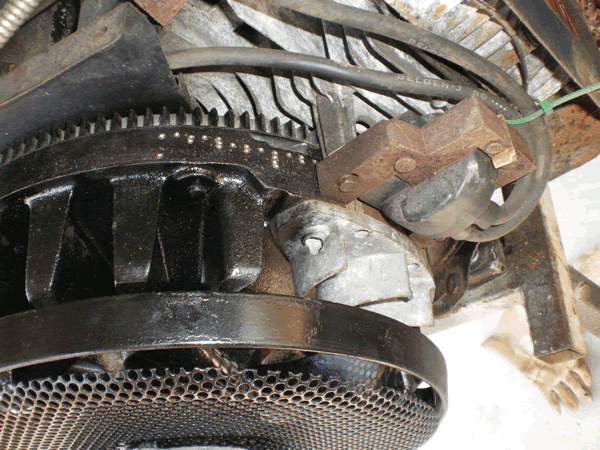
Stock ignition w/marks
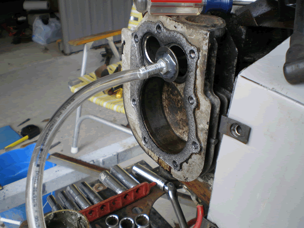
Valve lapping with hot glue
preheat bolt and valve with
propane torch, use tubing
and drill after cooled.
Engine Combustion Dynamics

The process of burning the fuel in the combustion chamber has always been the most misunderstood concept by people who modify engines and tune engines. This page should help to understand how the many factors determine the resulting engine performance:
- Gas Burn Duration
- Gentlemen, Start Your Ignition
- Gas Burn Rate
- Snowball Effect Burn Rate
- Compression Temperature Rise
- Power Stroke
- Turbulence, Squish & Quench
Throughout this discussion, gas refers to the mixture of air and fuel. The ideal burn duration is when the peak combustion pressure (PCP) (may also be called peak pressure point (PPP)) occurs at about 15-17 crankshaft degrees after top dead center (ATDC). This point applies the greatest burn pressure force on the crankshaft at the optimum crankshaft angle and for the maximum possible power stroke duration. When the engine achieves PCP at 15-17 degrees ATDC then Maximum Brake Torque (MBT) is produced. Shift this PCP position and less MBT is produced.
Because the gas combustion is designed to burn at a constant rate, the ignition start time must occur long before the PCP 16 crankshaft degrees ATDC. This is where things start getting critical.
Gentlemen, Start Your Ignition
It should be noted that the faster the engine is turning, the shorter the time for the crankshaft angle to reach that 16 degrees ATDC position (PCP). The burn time of the gas is controlled by the chemical makeup of the fuel itself, the temperature of the fuel, and how well it is mixed with the required oxygen. Octane additives do not change the burn rate of the gas. Racing engine fuel has a different chemical design so that it will burn faster to keep up with high RPM engines. Octane rating is NOT involved in this fuel burn time, regardless of what rumors you may have heard or may have said yourself. Combustion chamber shape will also affect burn time, and that will be explained later.
As the engine RPM increases, the ignition spark must be advanced tens of crankshaft degrees to have the peak combustion pressure (PCP) occur at 16 degrees ATDC. When the spark timing advance results in MBT, this is referred to as the MBT ignition timing point. As the engine RPM increases, the MBT ignition timing point must be advanced to keep PCP at 16 degrees. This is why you need a timing advance curve based upon engine RPM.
Several factors affect the burn rate (flame speed) of the gas. A common misconception is that octane increases the burn rate, but that is just not true. Octane increase increases the temperature required to ignite the fuel. The chemical properties control the fastest burn rate that the fuel can achieve. With HHO mixed in, the fuel chemical properties are altered, and the fuel now burns faster.Without HHO the air-fuel ratio (a/f/r) affects burn rate. Mixtures with a/f/r of less than 11:1 have little chance of burning (to rich), and a/f/r greater than 20:1 have little chance of burning (too lean). The fastest burn rate is at 17:1 but that is far to lean for reduced emissions, and way to lean for maximum power. Best power is achieved at an a/f/r of 12.6:1. With HHO enhancement all these a/f/r values will surely change. This change is what enhances the fuel burn and resultant engine efficiency.
Charge density affects the gas burn rate. A higher charge density burns faster. Charge density is a function of gas pressures and gas temperature. As charge density increases, burn rate also increases.
Homogeny of the gas affects the gas burn rate. Homogeny refers to the uniform distribution of air and fuel molecules within the gas mixture. As we mentioned earlier, the a/f/r affects burn rate, so homogeny also affects burn rate. Homogeny also introduces another issue concerning failure of ignition. If the localized a/f/r where the spark plug is located is to lean or to rich due to poor homogeny, then the spark plug will fail to ignite the gas, and that power stroke will be missed. This concept is referred to as the probability of ignition. The better the homogeny, the greater the probability of consistent ignition for each power stroke.
Because poor homogeny can cause ignition failure, a longer duration spark discharge into the spark plug is better than a shorter discharge duration. The turbulence and swirling actions due to the intake port shape and piston motion, may very well replace that lean mixture with a normal mixture while the spark is still arcing. When this happens, then the probability of ignition is improved.
Multiple sparks can help to overcome the failed sparks (due to homogeny problems) but multiple sparks will not make the combustion gas burn any faster. Dual spark plugs could make the resultant gas burn time shorter because of two burn sources. Sort of like burning a candle from both ends. The candle will burn faster this way, and so will the combustion gases. But each end of the candle still burns at the same rate. A rotary engine is the exception, and uses multi-spark dual spark plugs to compensate for poor homogeny due to the abnormally long combustion shape of the rotor in conjunction with the ported intake gas flow.
Dual ignition spark plugs on an aircraft can help with poor homogeny. If the a/f/r at one spark plug is to lean, then the other spark plug may have an a/f/r that is just right. The dual plugs will increase the probability of ignition. Since the two spark plugs are in separate physical locations, when both ignite the gas, the total burn time will be less because they are both creating a burn flame front which will burn all the gases faster (both ends of the candle again).
Incidentally, most aircraft engines have a large cylinder bore, which guarantees more occurrences of poor homogeny blobs within the combustion chamber. Dual spark plugs are necessary to regain acceptable probability of ignition which is inherently poor with large bore cylinders.
Can dual spark plugs develop more power? That is a tough question. Can the dual plugs get more power from the fuel, no they can't. Can the engine produce more power using them? Yes it can, here is how. By lighting the candle at both ends, the effective burn rate of the gas is increased. This means that the ignition timing can be retarded a little bit and still achieve MBT. This retarding of ignition timing will decrease the combustion gas pressures before TDC, which will reduce the force required to move the piston on up to TDC. This reduced drag effect on the pistons, will increase the pumping efficiency of the engine. Increased pumping efficiency results in less drag on the engine and more resulting engine ouput power. We will return to this pumping efficiency topic a little later.
It appears that significantly more power is developed with aircraft engines using two magnetos. This is apparent because the RPMs fall with one mag only. But there is a little slight of hand here. Remember that the one mag spark plug is off center on the combustion chamber, therefore the burn time will take longer (1-1/2 to 2 times longer than dual plugs). This longer burn time will delay the peak combustion pressure (PCP) beyond 16 degrees ATDC, which will reduce MBT. This is because the mag ignition timing setting was depending upon the shorter burn time. Since the PCP is later, then the resulting MBT is weaker. Therefore two mags don't develop significantly more power. One mag just develops less power due to the burn rate delay which effectively reduces MBT. The engine power output increase using dual magnetos is the slight increase in engine pumping efficiency. The engine RPM drop that you hear on one mag results from the increased burn time, delayed PCP, and lower MBT with one spark plug operation.
Inert effects also determine the gas burn rate. Inert effects include nitrogen gas in the air we breathe, but we can't do anything except ignore it. Inert effects also includes cold chamber walls (cold relative to the hot burning gas). The cold metal walls tend to reduce gas temperature which can quench the gas from burning, or at least slow it down due to temperature drop. Quenching will be described in more detail later.
Chamber shape and spark plug location can also affect burn rate. A hemispherical chamber with a high surface to volume ratio, will cool the gas more, and make it burn slower (reduced charge density). Those engines need more advanced ignition timing to compensate for this slower burn time. This slower burn time also reduces pumping efficiency.
The spark plug location also affects burn time as mentioned above. To use extremes as examples, if the spark plug was located at one edge of the chamber, it would take twice as long to burn all the gas across the chamber as a spark plug located in the center of the chamber.
OK, lets see how all this stuff works together. In order to determine when to fire the ignition plug, many of the above factors must be brought into play. I have already explained that when the spark plug starts the burn process, the burn process takes a finite time. During this time, as the burn continues, the burning gas volume expands
Most engines require that the ignition spark commence tens of degrees before top dead center (TDC) of the crankshaft. For this test engine example, we will assume that 23 crankshaft degrees BTDC is the MBT ignition point for a PCP of 16 degrees at a 3000 RPM.
At 23 degrees BTDC, the ignition coil fires, and the high voltage ionizes the gas between the spark plug electrodes. At some point of ionization, the ignition spark arcs across the gap and starts the burn process. This happens while the piston is still moving towards the cylinder head. Cylinder pressure is now increasing because of both the piston advancing towards the head (compression) and also because of the expansion of the burning gas. Because the gas is burning and not exploding, this pressure rise remains linear and within the design limits of the engine, while the piston continues to move closer to the head. At about 10 degrees BTDC, the burning expanding gas pressure is about equal to the compression pressure of the piston motion alone. During that last 10 degrees to TDC, we are more than doubling the cylinder compression pressure and charge density, because of the burning gas and its snowball expansion effect. This speeds up the gas burn rate, which makes the gas expand faster, which speeds up the burn rate, which makes the gas expand faster, which........
One thing is required to cause the gas to spontaneously explode, causing detonation, and that one thing is excessive heat. As you may know, compression of gas generates enough heat to ignite the fuel in a diesel engine without a spark plug. The diesel engine has a much higher compression ratio (about 22:1) to accent this compression heating effect. The gasoline engine has a much lower compression ratio than a diesel (8:1 - 12:1), which will have less compression heating effect, but will have some heating effect just the same.
The plan here is to keep the gas burning and expanding as the piston reaches the top of its stroke, and at the same time, never increase the gas temperature to its spontaneous combustion temperature. This is where gasoline octane comes into play. Increasing the octane rating of gasoline, increases the temperature required to promote spontaneous combustion of the gas. As long as the octane rating is high enough, the gas continues a controlled burn and associated linear expansion rate as the piston approaches TDC.
While approaching TDC, this cylinder pressure acts as a brake and resists the rising piston motion. This braking action steals power from the engine. This concept is referred to as the pumping efficiency of the engine. The sooner the burn rate starts, the more the engine pumping efficiency will be reduced. At TDC, the combustion chamber shape can also add additional virtual octane to the gas through the process of quenching the temperature of the gas, which we will explain shortly.
By the time the piston crosses TDC, we have some pretty serious burn rate and gas expansion happening here. This is due to the snowball effect of pressure rise and temperature rise as the piston approached TDC.
Now the piston is going down and the cylinder displacement volume is increasing. Thanks to the tremendous burn rate that has now been achieved (remember the snowball effect) the burning and expanding gases are expanding faster than the cylinder volume is increasing, so power stroke force is applied to the piston and pushes it down. In most auto engines, this compression pressure is now approaching 800-1200 psi. This burn rate continues to raise the cylinder pressure until about 16 degrees ATDC (about 1200-2500 psi) which is peak compression pressure (PCP). The piston is now receiving maximum force from the power stroke, referred to as maximum brake torque (MBT). If all the gas stays below spontaneous combustion temperatures during this time, then the maximum cylinder pressure will power the piston down with great force and for the longest possible duration.
As the piston moves further down past PCP, and the expanding gas continues to burn, a point is reached where the expanding gases start to burn out, and can't keep up with the increasing cylinder displacement. When this happens, the force applied to the piston by the expanding gas starts to diminish, and the power stroke is rapidly nearing its end. This usually happens at 20-25 degrees ATDC. Hopefully the gas has all been consumed by this time.
This concludes a normal power stroke which had no pre-ignition and no detonation.
As mentioned earlier, the shape of the combustion chamber can help to prevent detonation in two ways. The shape of the piston crown as it approaches the cylinder head, can create tremendous turbulence in the gas. This squishing of the gas mixture causes swirling and tumbling actions which causes shear tearing of the air & fuel molecules, which causes better homogenization. This improved mixing of the gas makes the gas burn faster. The same gas when burned faster has less time for spontaneous combustion. The faster the burn, the less time that is available for detonation to take place.
Another advantage of a faster burn is that ignition spark doesn't need as much advance. With less ignition advance, there is less time to build burn pressures before reaching TDC. This reduces braking action to the piston compression pressure, which increases pumping efficiency of the engine. This results in less power wasted to pump the engine cylinders.
Quench is quite another story. It is reasonable to expect that the gas in direct contact with the metal cylinder walls, piston crown, and the cylinder head surface; would be cooler because the metal absorbs heat from the gas (the metal is cool as compared to the burn flame temperature which can reach 5000F degrees). Because this thin layer is cooler, it does not burn and results in what is called a boundary layer of gas attached to the metal surfaces. This boundary layer is only a few molecules thick, but acts as an insulator which keeps the burning gas temperature from direct contact with the metal engine parts. This contains the gas burn temperature and prevents imparting excessive heat directly into the metal engine parts, which could melt aluminum parts. Like all insulators, it leaks some combustion heat into the metal parts and the engine cooling system must absorb that heat.
At TDC, portions of the piston crown get within about .040 inch from the cylinder head (squish region), and the close proximity of boundary layers quenches any attempt for gas in that region to burn. The .040 inch gap is hundreds of times thicker than the boundary layers, but the cooling effect quenches any gas trapped there. When that gas cannot burn, it reduces the chamber temperature which results in less heat available to cause detonation during the time from TDC to 16 degrees ATDC (after the squish time). This cooling effect is referred to as virtual octane because the cooler gas escaping the squish area as we leave TDC, steals heat from the burning gas, which reduces the chances of spontaneous combustion. This quenching effect results in a virtual octane increase. It has been found that the squish region has little effect if the piston to head clearance is 0.060 inch or greater. The optimum quench clearance is 0.040 inch.
This
concludes our combustion theory page. Go to our detonation
theory page to understand what happens when this linear burn rate goes
wrong and detonation takes place.
contact Lynn and let him know what you would like to contribute.
Return to top of page. Return to HomePage
Copyright
© 2009 by Lynn W. Graves
Reproduction or republication for commercial use
prohibited without express written permission
See website rules for further legal information
Website owned and operated by Lynn W. Graves.
Last updated (29Dec08
), lynn@whatifdyno.com