
Wide-band O2Sensor AFR Measurement
Fuel Flow Consumption Measurement
Adjustable Ignition Timing for MBT

Click images for larger
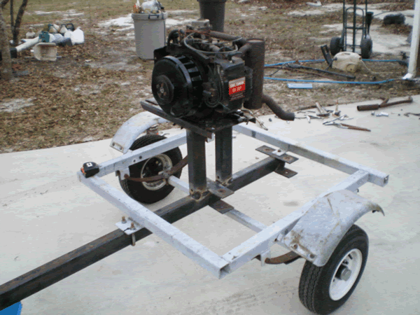
Fan Shroud
Beginning of engine stand
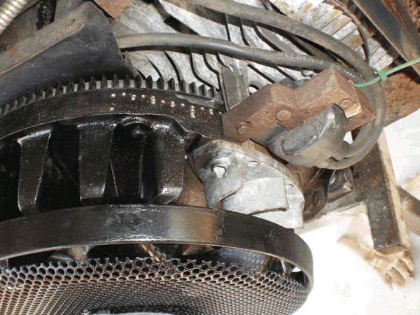
Stock ignition w/marks
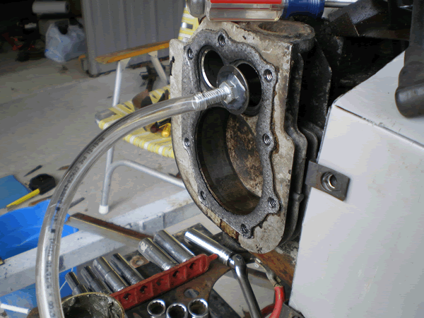
Valve lapping with hot glue
preheat bolt and valve with
propane torch, use tubing
and drill after cooled.
Now expect time to continue this project in late September, 2010
Today all I hear is speculation about HHO, ION ignition and water vapor. I am tired of you-tube type videos that drone on and on yet provide few if any facts. So I decided to build a poor man's dyno engine test stand that can measure all the parameters in doubt. Once this poor man's dyno is completed, then we can get the factual answers to all those speculative what-if-dyno questions. Several attempts have been made with inadequate engine test stands using electric generators, but those tests were inconclusive due to the inability to measure adequate test parameters.
This poor man's dyno (what-if-dyno) will answer once and for all, those what-if-dyno questions that we all have. In addition to these listed experiments, I may also conduct other experiments within the capabilities of this engine test stand as requested by you. I will provide you-tube type videos which actually provide information and not just watch some device operating. Constructive criticism is always welcome here, so provide any recommendations that you think would improve this project. This is a one-man project so far and additional support would be appreciated.
What If Dyno Experiment Expectations
1. Determine if engine air/fuel ratio affects air intake flow and intake
vacuum for a given RPM.
2. Determine what effect water vapor has upon engine MBT, air/fuel ratio,
and fuel consumption
for a given RPM.
3. Determine what effect HHO enhancement has on air/fuel ratio.
4. Determine what effect HHO enhancement has upon maximum brake torque
(MBT) timing.
5. Determine what effect HHO enhancement has upon exhaust gas temperature.
6. Determine what minimal percentage of HHO has maximum effect upon engine
effeciency
and/or power.
a.
measure air intake flow rate without HHO at engine given RPM.
b.
measure air intake flow rate with HHO same engine RPM.
c.
difference is the HHO flow rate being ingested.
7. Determine if HHO enhancement improves engine effeciency and/or power.
8. Experiment to develop a PIC Microcontroller ignition system that has
operator configurable
ignition timing adjustments
while the engine is running, and works with all current ignition
sytems on modern vehicles. It
will intercept the baseline timing before the ECU which
will fool the ECU yet allow
the ECU to manage the ignition timing using this false baseline.
9. Experiment to develop an ION ignition timing system capable of automatic
maximum brake
torque (MBT) adjustment.
Requirements and Features
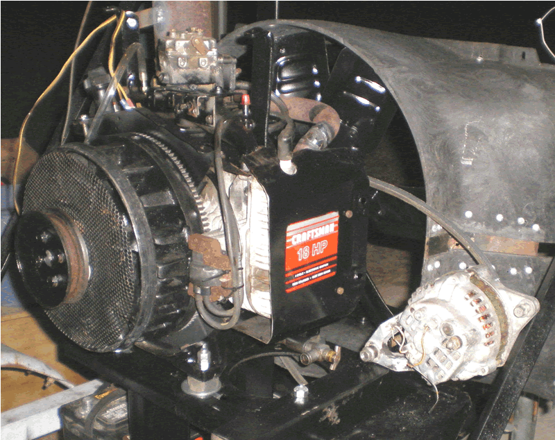
1. 18-horsepower Briggs twin cylinder engine with 28.2-cu-in (0.462-liters)
displacement.
2. Use a 7-blade truck cooling fan air load which remains constant for
a given air temperature
and humdity (air density) during
daily operation. The fan air load allows selection of any
operating RPM to obtain desired engine
load condition.
3. On board battery charging alternator with measured output current that
can be switched
on and off.
4. Engine intake manifold vacuum gauge.
5. Engine RPM tachometer.
6. Heated wideband oxygen sensor to measure and adjust the fuel mixture.
Unheated narrow band oxygen sensor
to simulate most automobile readings.
7. Carbruretor with adjustable power mixture control to set desired air-fuel
ratio using the
oxygen sensor.
8. Measured fuel flow indicator.
9. Fixed throttle plate settings (no governor) to adjust precise engine
load settings
(RPM with prop = load).
10. Measured exhaust gas temperature to evaluate engine load and operating
stress.
11. Measured cylinder head temperature to detect engine operating stress.
12. Capability to measure engine air intake flow rate.
13. Capability to measure external HHO gas intake flow rate (to be mixed
with the air flow rate).
14. Capability to dial in ignition timing settings while the engine is
running to determine maximum
brake torque (MBT) for
that RPM with a constant load.
Completed Dyno building Goals
1. Make repairs to engine to place in normal operating condition.
2. Mount engine, engine controls, and and fuel tank on a small boat trailer.
3 Install battery charger alternator, ampmeter, and alternator-on/off
switch.
4. Machine pulley and weld 7-blade fan to this pully.
5. Install oxygen sensors in exhaust system.
6. Install exhaust gas temperature sensor and cylinder head temperature
sensor.
Pending Dyno building Goals
7. Modify throttle plate linkage for accurate fixed throttle settings.
8. Modify stock electronic ignition system so that engine timing can be
easily adjusted with engine running.
Will be used to adjust timing for maximum RPM with fixed throttle
plate to determine maximum brake torque
(MBT) under that load and atmospheric condition.
9. Devise and install engine tachometer.
10. Devise a method to measure the air intake flow to the engine.
a. use a low cost hand-held
annometer with intake plumbing.
b. Use a "Y" in the
plumbing to pull HHO from the HHO cell.
contact Lynn and let him know what you would like to contribute.
Return to top of page. Return to HomePage
Copyright
© 2009 by Lynn W. Graves
Reproduction or republication for commercial use
prohibited without express written permission
See website rules for further legal information
Website owned and operated by Lynn W. Graves.
Last updated (01Aug09
), lynn@whatifdyno.com